Rogers FR4 Hybrid PCB Stackup Design Guide
Introduction
Many engineers face the same challenge when designing modern RF products.
High-frequency circuits require low-loss materials, while system boards still depend on cost-effective FR4 structures.
Designers widely use Rogers FR4 hybrid PCB stackups to solve this conflict in real production designs. They combine RF-grade laminates with standard FR4 layers in a single manufacturable structure.
This guide explains how to design, evaluate, and manufacture these hybrid stackups.
Material Properties Comparison
Rogers and FR4 behave markedly differently under GHz frequency operation and thermal stress conditions.
Rogers Laminates
Rogers materials are engineered for stable dielectric performance in RF environments.
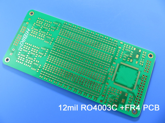
Common grades include RO4350B, RO4003C, RO3003, and PTFE-based laminates such as rogers 5880 pcb materials.
These laminates maintain stable dielectric constant across temperature and frequency ranges.
They also provide low dissipation factor, which reduces signal loss in RF transmission paths.
FR4 Characteristics
FR4 remains the most widely used PCB substrate in electronics manufacturing.
Its dielectric constant typically ranges from 4.2 to 4.8 depending on resin system.
FR4 offers good mechanical strength and low cost for mass production environments.
However, signal loss increases significantly at frequencies above several GHz.
Key Mismatch Parameters
Designers often do not give CTE mismatch enough attention during hybrid stackup design.
Z-axis expansion differences between Rogers and FR4 can generate internal mechanical stress.
| Property | Rogers RO4350B | FR4 |
| Dielectric constant stability | High | Medium |
| Loss tangent | ~0.0037 | ~0.02 |
| Thermal expansion (CTE z-axis) | Low | High |
| Cost | High | Low |
CTE behavior often impacts reliability more than dielectric constant mismatch in real fabrication.
Bonding Material Selection
Bonding material is a critical decision in a Rogers FR4 hybrid PCB stackup. The interface between Rogers and FR4 must handle different resin systems, thermal expansion rates, and lamination behavior. Engineers often use Rogers-compatible bonding films like 4450B or 4450F.
They offer better adhesion and process stability than standard FR4 prepreg.
Using generic FR4 prepreg at this interface can create weak bonding, especially after reflow or thermal cycling. For reliable production, engineers should review resin flow, curing temperature, surface treatment, and fabricator experience before finalizing the stackup.
Root Causes
CTE mismatch is a major contributor to interface stress during thermal cycles.
Moisture absorption differences also create expansion imbalance during reflow processes.
Surface residue reduces bonding strength during lamination stages.
Process Controls
Plasma treatment improves adhesion between dielectric interfaces before lamination.
Controlled ramp-up profiles reduce internal stress during pressing cycles.
Pre-baking FR4 materials reduces moisture-related expansion issues.
Drilling and Via Design
Drilling and via design play a critical role in rogers fr4 hybrid pcb performance and long-term reliability.
Mixed dielectric structures introduce different mechanical and thermal behaviors during drilling and plating processes.
Rogers materials are harder and more abrasive than standard FR4 laminates.
This increases drill wear and affects hole quality consistency in high-volume production.
FR4 drilling is more stable, but resin smear can still occur under high-speed CNC conditions.
When combined in a hybrid pcb stackup, tool control and process tuning become more important.
Aspect Ratio and Plating Reliability
Via aspect ratio directly affects plating quality in hybrid structures. When the hole becomes too deep relative to its diameter, copper deposition becomes less uniform. This often leads to thinning in the middle section of the via barrel or internal void formation.
Hybrid stackups make this more sensitive because Rogers and FR4 respond differently during thermal and mechanical processing. Even small distortions during lamination can affect plating consistency.
In real fabrication, engineers rarely rely on theoretical limits alone. Instead, they follow fabricator-defined aspect ratio windows based on actual plating capability.
Standard Rogers FR4 Hybrid Stackup Structures
4-Layer Hybrid Stackup
A common 4-layer structure uses a simple functional separation:
- L1: Rogers RF signal layer
- L2: Ground reference plane
- L3: FR4 power or digital routing
- L4: Rogers or FR4 depending on design needs
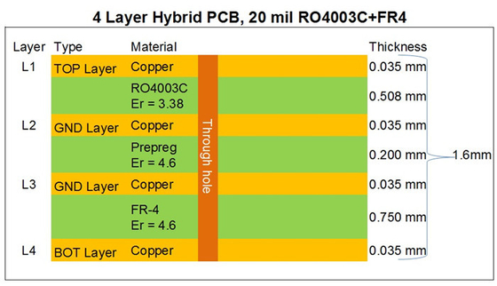
This structure fits compact RF modules and IoT devices.
It provides a basic balance between cost and RF performance.
6-Layer Hybrid Stackup
Six-layer designs improve isolation between RF and digital domains.
Designers place Rogers layers closer to the outer surfaces.
FR4 layers remain inside for routing and power distribution.
This configuration reduces noise coupling between system sections.
Signal integrity improves because of better reference plane control.
Layout flexibility increases for mixed-signal designs.
8-Layer and Above Stackups
High-layer count boards support complex RF and digital integration.
These structures appear in radar and 5G infrastructure systems.
RF traces stay confined to Rogers-defined regions.
Digital routing remains inside FR4-based sections.
We avoid cross-domain routing to reduce signal distortion.
Stackup planning becomes critical at this complexity level.
Impedance Control Challenges in Hybrid Stackups
Impedance control becomes more complex when two dielectric materials coexist in one PCB.
Each material introduces different electric field distribution and propagation characteristics.
Rogers layers typically maintain tighter impedance tolerance at high frequency.
Stackup design must compensate for variation that FR4 layers introduce.
Signal integrity issues often originate from inconsistent dielectric transitions.
This occurs when traces cross boundaries between Rogers and FR4 regions.
Key impedance control practices include:
- Maintaining continuous reference planes under signal routing
- Avoiding cross-material transitions in RF trace paths
- Using simulation tools for field distribution verification
Even small stackup deviations can shift impedance by several ohms at GHz levels.
Manufacturing Process Considerations for Hybrid PCBs
Hybrid PCB fabrication requires more complex processing than standard FR4 boards.
Mixed material integration often requires multiple lamination cycles.
Each lamination stage must maintain precise alignment between layers.
Misalignment can affect impedance and signal propagation consistency.
Electrical testing becomes essential after final fabrication stages.
Engineers commonly use time-domain reflectometry to validate impedance.
Typical manufacturing sequence includes:
- Inner layer imaging and copper patterning
- First lamination cycle with mixed dielectric materials
- Drilling and via formation processes
- Secondary lamination for multilayer integration
- Electrical testing and impedance verification
Manufacturing tolerances directly influence final RF performance outcomes.
When to Use Rogers FR4 Hybrid Stackups
Hybrid stackups are not needed for every PCB design. They become valuable when RF circuits, digital control sections, and power networks must share one board without using full Rogers material across the entire stackup.
For many projects, FR4 remains suitable for low-speed digital routing and power distribution. When RF paths move above 1 GHz, especially in long traces or sensitive front-end circuits, FR4 loss can start to affect signal quality. In these cases, a Rogers FR4 hybrid PCB offers a practical balance between RF performance and cost control.
A hybrid stackup is usually worth considering when RF and digital circuits share the same PCB platform, full Rogers construction is too expensive, and only selected layers need low-loss dielectric performance.
Engineers can use a PCB Stackup Design Tool to compare different hybrid layer structures before layout begins. This helps review Rogers layer placement, FR4 core usage, reference planes, and possible impedance risks early in the design process.
Application requirements should always drive the final stackup choice, not material preference alone.
Conclusion
Hybrid PCB design requires coordination between electrical engineering and manufacturing constraints.
Material selection alone does not guarantee reliable RF performance.
The success of a rogers fr4 hybrid pcb depends on stackup accuracy and process control.
Engineers must validate impedance, thermal behavior, and bonding reliability early in design.
A properly designed rogers pcb board material system balances cost, performance, and manufacturability.
Advanced materials like rogers 5880 pcb offer further performance gains in extreme RF applications.
Hybrid architectures will remain essential for future high-frequency electronic systems.
Need Help With Your PCB Stackup?
Use our PCB stackup design tool or contact our engineering team for material selection, impedance review, and production support.
Contact Us